
by Robert Buchholz
NOTE: It is critical that you take your time and follow the manufacturers directions to make this conversion successful. This is just an example of my conversion, and should not be substituted for the directions.
Keep these points in mind before starting this conversion
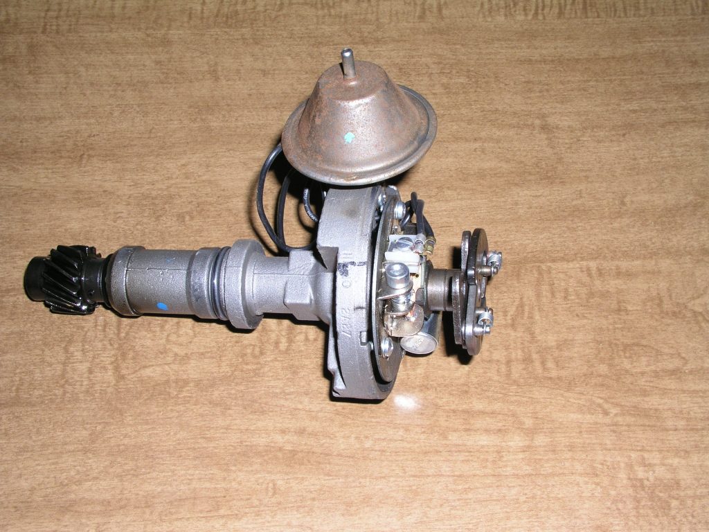
- Start with a good distributor (mine was recently replaced with a reman)
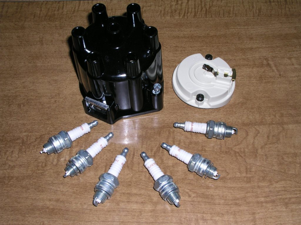
- Replace the cap, rotor, and spark plugs. They are cheap in comparison to the aggravation of chasing electrical gremlins
- Get all of the parts together before you start. You don’t want to be chasing parts mid-job.
- Take your time, if you rush this install it will backfire (no pun intended)
- Read the directions! I know it is against human nature, but force yourself and read the directions through beforehand and follow them throughout the install
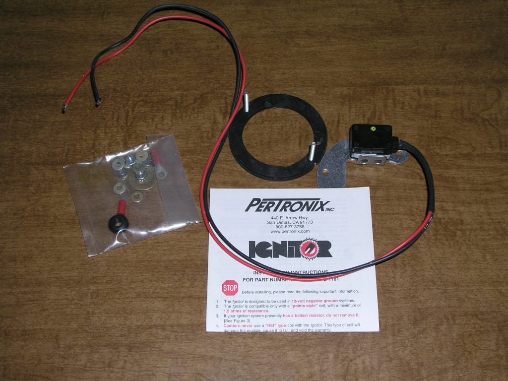
I picked up my Pertronix kit from Eldon at Valley Automotive Specialties in Medical Lake Washington. He would have installed it for a very reasonable price, but I wanted to do this article, so I chose to install it myself.
Here is the parts I started with:
Tools Needed:
- Paint marker
- Wrenches to remove distributor
- Ratchet and spark plug socket
- Nut drivers
- Screwdriver
- Pin punch and hammer to remove distributor gear if needed
- Timing light
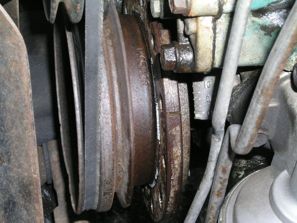
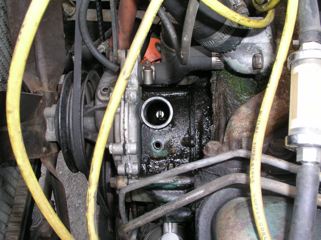
Safety first, disconnect the battery cable. Then, just to retain your sanity when reinstalling the distributor, set the timing to top dead center cylinder 1 and note the position of the distributor body and rotor. I like to make a mark on the distributor body and the engine where the rotor is pointing.
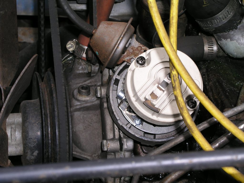
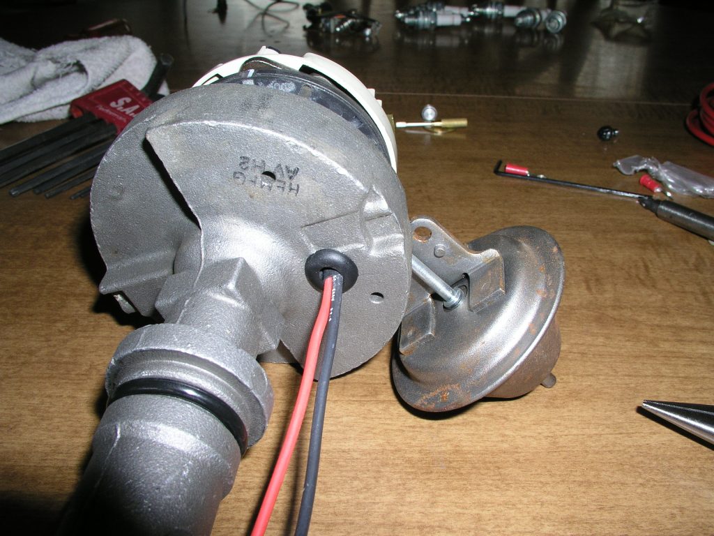
Remove the hold down clamp and remove the distributor. Take note of the oil pump driveshaft position, as it will help with re-installation later. Move to a flat clean place to work. I chose the dining table, but my wife is very understanding of my disease. Any neat workbench will do, but the cleaner the better. It would also be a good idea to put a plug or rag in the open distributor hole to prevent dirt from getting into the engine.
Loosen the captured screws and remove the rotor from the mechanical advance assembly. Remove the three hold-down screws and remove the points and condenser. Keep the screws for mounting the pickup module later. You can keep the points around in a baggie in the glove box. If this ignition should ever fail, you can reinstall them with minimal effort, and get yourself home. However, I have been running this ignition without issue for years now.
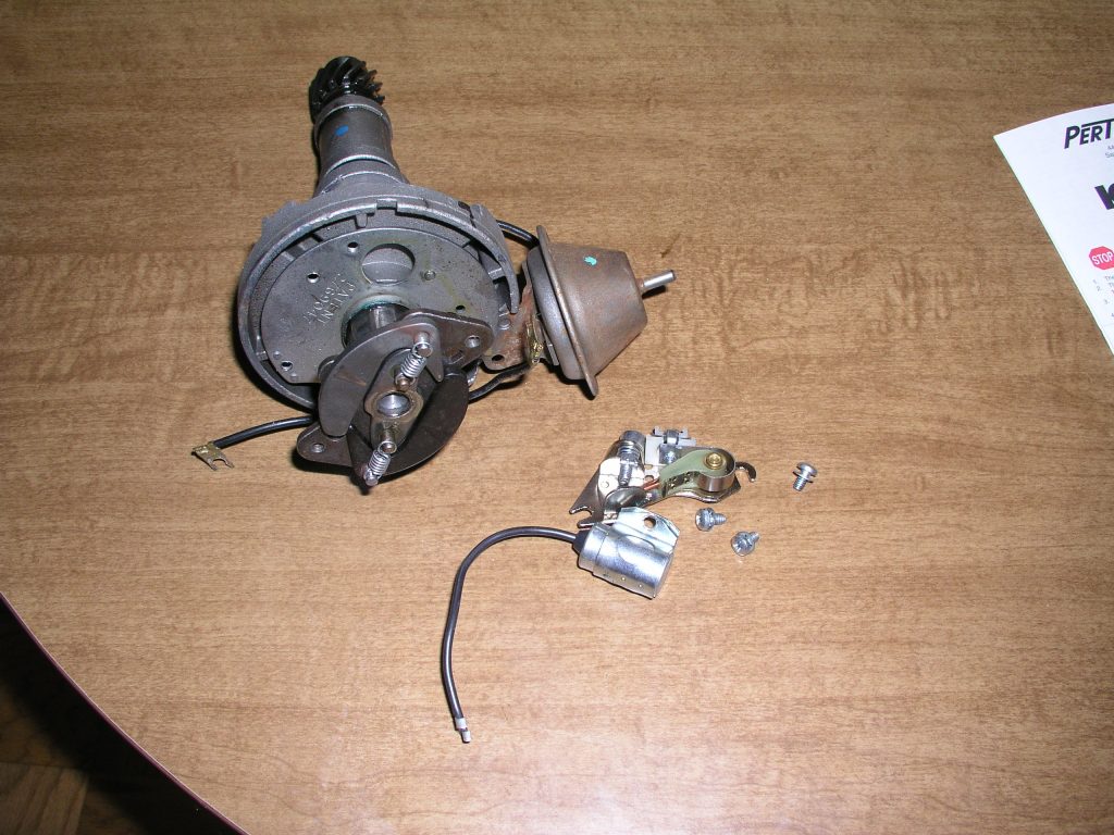
Install the trigger ring by holding at an angle and sliding over the mechanical advance assembly. Slide the threaded studs up through the mounting holes for the rotor. Make sure the notch on the magnet ring is on the side of the advance assembly with the square hole. Next, you will have to remove the captured screws from the rotor. Just push them up until they get a bite in the plastic, and unscrew them. The rotor will be held on by the studs of the trigger ring. Put the washers and 6/32 nuts on the studs and tighten.
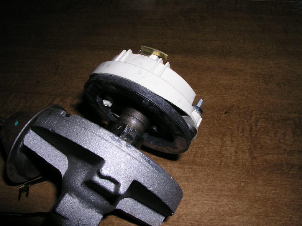
Install the pickup assembly. It will screw on in place of the points using the points screws. Once installed, you will need to check all of the clearances. The instructions I indicated a minimum of .010″ and a maximum of .060″ Also, I found that my pickup had some casting flash sticking up, so I carefully removed it to avoid erroneous measurements. First measure with all of the slack down towards the gear. You may have to tweak the pickup bracket, or shim the trigger ring to get this measurement within specs. Then, push all of the slack up towards the rotor and check clearance there, you may have to shim the drive gear to limit gear climb as I did on mine. You do this by removing the roll pin that retains the drive gear, removing the drive gear and installing shims. I recommend determining the excess gap you need to make up and measuring the shims, so you only have to do this once. Make sure you keep rotating the assembly and checking clearance in the lowest/highest place as applicable.
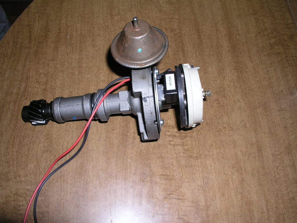
Once your clearances are good, you can thread the wires from the pickup down through the hole in the bottom of the distributor and install the grommet. You can crimp the ring terminals on the wires now, or wait until you have installed the distributor and trim them to length. Make sure you tighten down all of of the screws and nuts. Et Voila! You have a completed distributor. However, were not quite done yet.
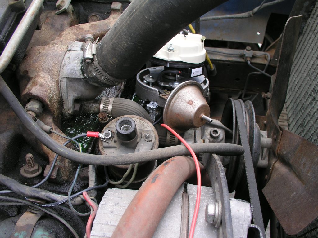
Reinstall the distributor, this will probably take a few tries to get the distributor body, the rotor, and the oil pump shaft to line up correctly. Once installed wire it up per the directions. Mine was red wire to the ignition switch side of the ballast resistor, so the module gets a full 12 volts. And black wire was wired to the negative side of the coil where the points used to connect. Do not bypass the ballast resistor unless you are replacing the coil and its instructions tell you to do so. Make sure you check and see how it should be wired for your engine and coil. Static time the engine by making sure the distributor body is pointed in a way that will make the rotor point at the #1 post of the distributor cap. Install the new distributor cap, and gap and install the new spark plugs. The Pertronix website recommended gapping the plugs .005″ wider than stock for the electronic ignition. Reconnect the battery and double check everything. Start your engine.
After you start your engine, time it by ear enough to get it running and warm it up. After it is warm, use a timing light to time it to manufacturer specs and enjoy. I have found this ignition has helped tremendously with cold weather starts and general reliability. Prior to installing this, my jeep would eat points like candy. You may want to install a “hotter” coil to gain some additional benefit, and possibly some additional plug gap for even better ignition.