
by Robert Buchholz
I added this page to document my upgrade to the alternator. This is a common upgrade, and may be common knowledge, but I felt it was good to document anyway. If you have information on an upgrade like this on the 4 cylinder version, please email me.
History
If you have a stock 66 – 71 Jeepster Commando with the Dauntless V6, you are probably painfully aware of the weakness of the stock alternator and regulator. Since Jeep is known for using parts from all the manufacturers, hence the mnemonic Just Everyone Else’s Parts, it is inexplicable to me why Kaiser Corporation decided to use a Motorola alternator and regulator on the vehicle rather than just run the tried-and-true Delco Remy design on their GM designed engine. Instead, they installed a Motorola A12NW528 alternator, and Motorola R-2-K-1 regulator, according to the service manual. During this same period, GM was using their 10DN externally regulated alternator design, and upgraded to the internally regulated 10si alternator design in the late 60’s. Some of this might be applicable to the 4-cylinder version, but I don’t have access to one to verify.
Problems
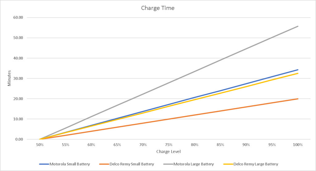
There are three major problems with the Motorola alternator that they used. The first problem was the poor performance of the alternator. The Motorola alternator was rated at 35 amps. With a car battery holding between 40 and 65 amp-hours, and with the car battery considered dead at half their capacity, it will take the Motorola alternator between 35 to 55 minutes to fully charge a dead battery, where the Delco would accomplish the same in 20 to 32 minutes. This is assuming that no other current is being used by the car.
Due to this poor performance, you could see noticeable effects like the headlights dimming when you set the heater fan to high on a cold night. The second issue is even more inexcusable. My Jeepster’s alternator mounting looked like it was cobbled together in a garage over a weekend. When you look at the alternators in profile, you will notice that the Delco alternator has a longer lower pivot casting than the Motorola.
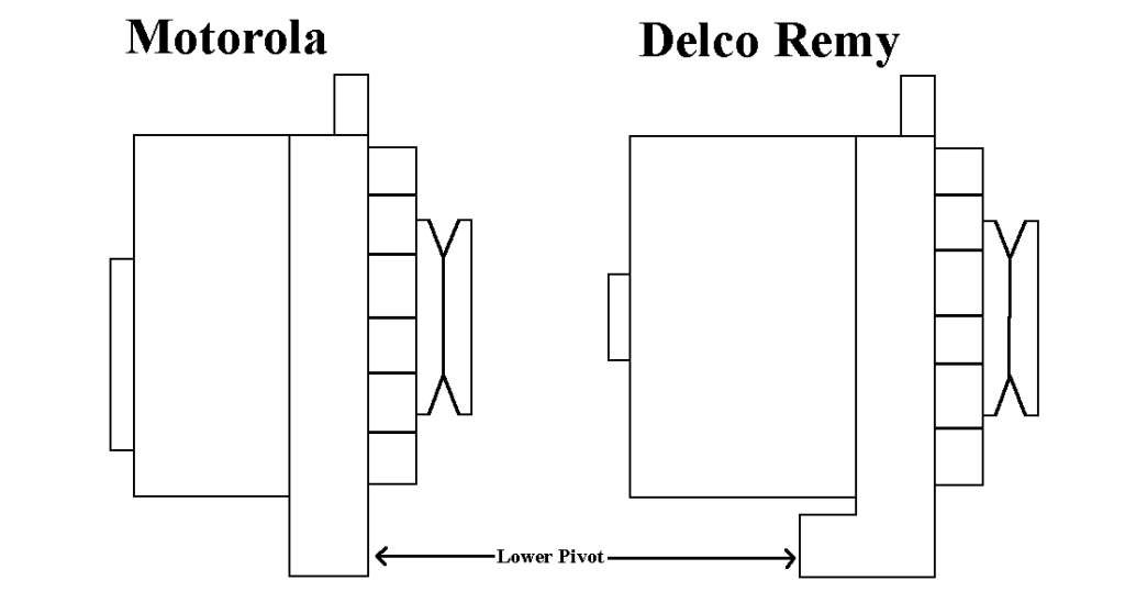
This difference means that the Motorola alternator needs to have spacers placed in the lower pivot to keep the alternator aligned with the main crank pulley. These spacers are inevitably damaged, lost, or deliberately thrown out causing the pulley alignment to be wrong. The Delco’s larger pivot fits the lower mounting bracket exactly (shocked gasp). All the other dimensions of the alternators are similar. The center-to-center distance from the pivot and the clamping bolt are the same or close enough to not matter. The diameter of the alternator body is the same. The only major difference is in the length of the alternator body, but that is all behind the pivot, so it doesn’t affect the alignment of the alternator in any way.
The third problem is not with the design, engineering, or capabilities. It is simply that it wasn’t used in many vehicles. That makes getting the alternator and regulator today more difficult. Many places don’t carry it, and those that do know they are rare and charge accordingly.
Options
The 10DN alternator of the time was similar to the Motorola. It put out 40 amps, but it also required an external regulator. The later 10si alternators are fundamentally identical in all of their mounting dimensions, so the 10si, used by GM from 1969 to 1983, is a great alternative. It has an internal regulator and is capable of 60 amps typically. The later 12si, used by GM from 1983 to 1987, alternator also has the same mounting dimensions. The front fan is different, but otherwise is effectively the same design. It has a higher output capacity between 78 and 94 amps, making it even better suited for demanding electrical systems. There are also 3rd party manufacturers that make these alternators in the 100-amp range. Keep in mind that many “performance” alternators are 1-wire alternators. These alternators are self-exciting, which means that they don’t have the field wire connection. Without this connection, you cannot wire in your charge indicator light. Another item you will want to pay attention to is the clocking of the alternator. The clocking is the position of the terminal location that the pigtail plugs into. I recommend the 12 or 3 o-clock positions so that the battery terminal is in a position that will easily be reachable by the wiring harness, but you should choose what works best in your application. If your clocking is wrong, you can pull the screws and re-clock the alternator if needed. The last item to keep in mind when sourcing your new alternator is the pulley. Many later 12si alternators had a serpentine pulley which will obviously not work with the v-belt system on the Dauntless.
Procedure
For starters you will need the following parts:
- Alternator (either the 12si or 10si will work. Make sure you get the right one for your application).
- Alternator Plug pigtail.
- AC Delco PT2288. Many companies make these after market.
- Crimp Connectors
- Butt connector
- Ring terminal
- Heat Shrink tubing (optional)
Tools you will need:
- Wrenches for loosening and tightening the battery terminal, locking bolt and pivot bolt.
- Crimpers for connecting the new wiring pigtail.
- Wire cutter/stripper for stripping pigtail wires.
- Voltmeter for checking new alternator output.
- Heat gun to shrink tubing (optional.)
First, disconnect your battery. I know this is the first step in many procedures in service manuals even when it doesn’t make any sense. However, in this case it is VERY important you do this. You will be working with the battery charging cable which is an unfused large gauge cable that can carry a lot of current. If you accidentally ground this wire, you run a real risk of blowing up your battery or starting a fire.
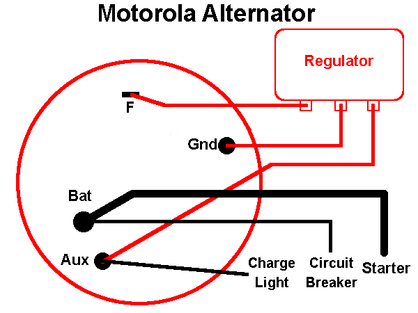
Next, remove the wires from the rear terminals of the old alternator. There are 4 terminals. Three wires will go to your regulator and should be in their own harness. You can safely remove and discard this harness. One of the 3 wires coming from the regulator should be red and should have a second wire on the terminal. This is the Aux terminal and is also connected to the charge indicator light. You will need to keep track of this wire. The other wires to keep track of is the main power connectors. One is a large wire going back to the main starter terminal, and the other is the main power feed to the circuit breaker in the cab. You will also need to keep track of these wires as well. The wiring is diagramed in the below image. You can remove the wiring marked in red. Keep track of the wiring in black.
Next, loosen the top locking bolt and bottom pivot bolt on the alternator. Rotate the alternator towards the engine to loosen and remove the belt from the alternator. Once the belt is off, you can remove the bolts completely and remove the old alternator. Inspect the lock and pivot bolts and replace if they are worn. A worn pivot bolt will cause problems with belt alignment.
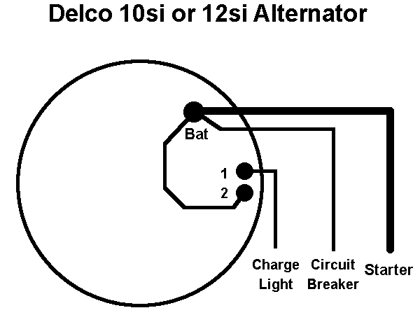
Add a ring terminal to the pigtail wire that connects to terminal 2, most likely the red one. Make sure the ring eye is large enough to go over the Bat terminal. This wire is strictly not necessary but looping it to the Bat terminal keeps it from dangling and gives the pigtail connection some stability. You can, if you want, run this wire back and connect it to the battery positive terminal. This wire is the sense wire, and tells the regulator what the output voltage is, so it can adjust the alternator output. The wire that connects to terminal 1 will be connected to the wire that was connected to the Aux terminal of the old alternator. Crimp these together with a butt connector, preferably one that has heat shrink built-in, or at least heat shrink over the connector afterwards.
Once the wiring is prepped, install the new alternator. Loosely attach the pivot and locking bolts. Re-install the belt and tension it. Connect the three wires to the battery terminal, 2 from the old harness, and the pigtail ring terminal. Plug in the pigtail to the side terminal. After these connections, your wiring should be connected like the following diagram.
Finally, re-attach your battery, and check the voltage. It should be about 12.7 for a fully charged battery. Check for shorts, which would indicate miswiring. Once it is good, turn your key on and verify the charge light comes on. Start the engine and verify the start light goes out. Check the voltage at the battery while the engine is running. You should see a voltage between 13 and 15 volts. If the voltage is the same as when the engine was off, the excite connection is most likely not working.
Next Steps
Now that you have a higher capacity for your vehicle electrics, it would be a good time to look at the article on upgrading your electrical system. There are weaknesses in the design that could lead to burned wiring or a fire.