
by Merl Howell
I have added this article to my page as the Merl’s Garage site that used to host this seems to be defunct. If you are the author, please reach out to me so I can give proper credit to your work. I apologize as there are many images that I could not recover from the original page
What’s so odd about this V6?
I’ve been hearing the term “odd-fire V6” ever since I got into the Jeep hobby. You hear the term a lot because the optional Dauntless 225 that went into the late 60’s CJ5 is such a popular swap into other Jeeps. I’d always wondered what people meant by “odd-fire”, and when I bought an M38A1 that had been the subject of a ’76 Buick 231 V6 swap my curiosity became even more pronounced. But it wasn’t until I decided to change my points type distributor to a GM HEI type that I became determined to find out just what “odd-fire” really means. I searched high and low on the web, even purchased a Buick repair manual just to try and gather information, but try as I might I couldn’t find any information on what was so odd about this engine. So finally I sat down and put my noggin to work one day and with a good bit of email help from Bill Lagler, not to mention a lot of scribbling, I think I’ve got it figured out. It’s actually fairly straight forward once you understand… So now, without further adieu, this is what’s so odd about the Jeep/Buick “odd-fire” V6.
First, the basics
The most important thing to understand before going through all this is the basic functionality of a four stroke gasoline engine. If you need a primer on engines and how they work, make a visit to How A Car Engine Works. Find some other good information specific to the Dauntless V6 on Adam Sparks’ Early CJ-5 Page.
One thing that I’d always heard about this V6 is that it was simply an early V8 that had two cylinders removed. Put this out of your mind. It may be true but its absolutely no help if you’re trying to understand how this engine works, trust me on this. And now a few facts:
| The cylinder numbering for the odd-fire V6 is 1-3-5 from the front down the driver’s side, and 2-4-6 down the passenger side. The firing order is 1-6-5-4-3-2. |
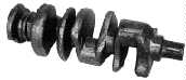 The Dauntless 225 and the odd-fire Buick 231 have a crankshaft with three journals that are offset at 120 degree intervals.odd-fire crankshaftLooking at the front of the crankshaft you would see the front journals at the noon position on a clock, the middle journal at the eight o’clock position, and the rear journal at 4 o’clock. The Dauntless 225 and the odd-fire Buick 231 have a crankshaft with three journals that are offset at 120 degree intervals.odd-fire crankshaftLooking at the front of the crankshaft you would see the front journals at the noon position on a clock, the middle journal at the eight o’clock position, and the rear journal at 4 o’clock. |
| Each of the three journals are shared by two pistons. The front journal is shared by cylinders 1 and 2, the middle shares 3 and 4, and the rear shares 5 and 6. Keep in mind that this means if one piston is fully extended towards the cylinder head, the other piston that shares that journal will not be. |
| This is a 90 degree V6, meaning that the two banks of cylinders are at 90 degrees to each other. Most V8 and some other V6 engines are also built at 90 degrees, but logic would dictate that 60 degrees would be more natural for a V6. For example the 2.8L V6 used in some late model cars is a 60 degree engine. |
| Since each journal is shared by two pistons, if one piston is fully extended towards the cylinder head the other piston sharing that journal will not be. For example, with number two fully extended number one will not be fully extended until the crankshaft rotates another 90 degrees (since the cylinder banks are at 90 degrees to each other). |
| The distributor shaft and rotor will make one complete rotation for every two rotations that the crankshaft makes. |
| Since an engine crankshaft always rotates twice per ignition cycle, most of the information here is presented as 0 to 720 degrees rather than just 0 to 360. The 720 degrees represents two complete rotations of the crankshaft. |
| As the crankshaft rotates, zero degrees is the beginning of the firing order cycle. This is actually when ignition takes place on the last piston and is also equal to 720 degrees in the rotation cycle. |
Enough basics
So combine the fact that the journals are offset 120 degrees and the pistons sharing a journal are fully extended at a 90 degree offset, with one rotation of the crank the pistons will fully extend at 90-120-210-240-330-360 degrees. This would make a lot more sense with a picture, but here’s a word/math explanation: With the front journal pointing straight towards the #2 cylinder (piston fully extended) we’re at zero degrees. The engine rotates clockwise 90 degrees and the #1 piston sharing that journal is now at full extension. During that 90 degrees of rotation, the middle crank journal has been getting closer to putting the #4 piston in it’s fully extended position, but since the journals are 120 degrees apart it still has to rotate another 30 degrees before it gets there. Once #4 is extended, we rotate another 90 degrees and #3 is fully extended (remember, 3 and 4 share a journal). Another 30 degrees and you’ve got #6, and another 90 gives you #5. So the pistons fully extend at 90-120-210-240-330-360 degrees because 90+30=120, 120+90=210, 210+30=240, etc.
Since that was for one rotation of the crank, if you follow it through the second rotation in the ignition cycle you’d get 450-480-570-600-690-720. Remember that what I’m talking about here is simply full extension of the pistons, remember that every other time a piston extends down a cylinder it is actually on an exhaust stroke..
Where’s the beef?
Ok, I suppose that stuff was actually background too. All right, enough background already! Here’s the good stuff.
| With the crank at 0 degrees, the engine rotates 90 degrees and fires on cylinder #1. | |
| The engine rotates 30 degrees, and #4 is at top center (TC) of it’s exhaust stroke. | |
| Rotate another 90 degrees and #3 (same journal as #4) is at TC of it’s exhaust stroke. | |
| Rotate 30 degrees, #6 fires. | |
| Rotate 90 degrees, #5 (on the same journal as #6) fires. | |
| Rotate 30 and #2 is at TC of the exhaust stroke. | |
| Rotate 90 and #1 is at TC of the exhaust stroke. | |
| Rotate 30 and #4 fires. | |
| Rotate 90 and #3 fires. | |
| Rotate 30 and #6 is at TC of the exhaust stroke. | |
| Rotate 90 and #5 is at TC of the exhaust stroke. | |
| Rotate 30 and #2 fires | |
| Repeat. |
This is a 12 frame animated GIF. Each of the 12 frames in the sequence represents one of the 12 lines in the table above. The left part of the image is a cut away view of the engine as seen from above, the right part of the image is a representation of the crankshaft as seen from the front. The red blobs indicate top center of an ignition stroke, the black blobs are top center of an exhaust stroke. Note the 1-6-5-4-3-2 firing order.
Putting it all together
If you add the the degrees of rotation between the “fires”, you get 90-150-90-150-90-150. Simply put, the engine rotates 90 degrees, fires on a cylinder, then rotates another 150 degrees before firing on the next, then 90 again, etc. On the distributor (which rotates only once in this cycle) this is equal to 45-120-165-240-285-360 degrees which is equal to a 45 and 75 degree spacing (half of the 90 and 150 degree spacing). even-fire crankshaft When they turned this engine into an even fire they left it as a 90 degree V6 and split the crank journals in such a way that would force it to operate at the evenly spaced 120 degree interval. If you can make it out in this picture,
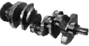
the even-fire crankshaft is a good bit more complicated looking, and rumor has it that splitting the crank journals like that made the crankshaft much weaker. The split journals on the even fire crank is also what made it possible for the even-fire 231 V6 to use evenly spaced lobes, each 60 degrees apart, on it’s distributor shaft.
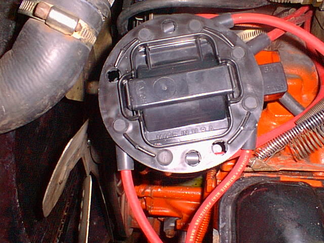
What about the distributor cap?
The distributor cap on these engines is a real source of confusion. If it has an odd-fire pattern that results in 45 and 75 degree spacing on the lobes around the distributor shaft, wouldn’t the distributor cap have that same sort of spacing? No, not in this case. What the original engine designers did was take advantage of the fact that the contact point on the rotor can be made longer than normal. Draw a circle that follows the circumference of the rotor’s outer contact, then draw a straight line from the center of the circle to one end of the rotor contact and another line to the other end. What you’ve just drawn is an angle of at least 15 degrees. Since the evenly spaced lobes on an odd-fire points type distributor cap are 60 degrees apart and the distributor shaft lobes are at 45 and 75 degrees, a little subtraction tells you that this will all work out. Simply put, 50% of the time ignition is taking place when the forward end of the rotor contact passes a distributor cap lobe, and the other 50% of the time ignition happens when the trailing end of the rotor contact passes a distributor cap lobe.
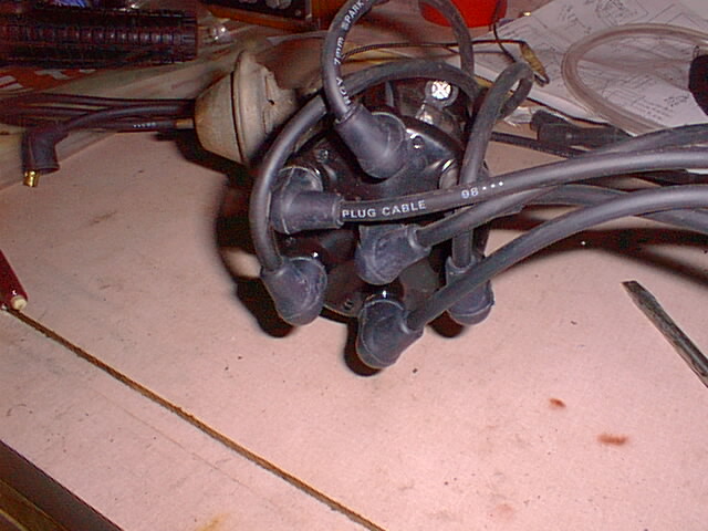
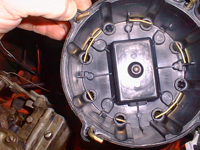
The GM HEI distributor and cap use a similar technique, but GM went one step further in order to save a little money (and perhaps to confuse hackers like us at the same time). GM made all HEI distributors, caps, and rotors the same for all of their engines no matter what the configuration. A V8 engine will use all eight lobes on the cap, a six cylinder will have two of the lobes “blanked” (unused), and a four cylinder will have four of the lobes “blanked”. GM got around the spacing problem by customizing the plug wire contacts on the inside of the cap for each engine type. The inside of a V8 cap would look just like you would expect, and the four cylinder cap would have every other lobe “blanked” so it would also look fairly normal. But for an odd-fire V6 they had to extend some of the contacts to account for the 45-75 degree spacing. Notice the word “some”. If you understand the concept that the rotor will cause ignition to occur every 45 and 75 degrees of rotation, and you look closely at the inside of the HEI cap above, you’ll notice that 75 degrees of rotor rotation from some of the contacts will wind up with the rotor pointing at open air. Simply put, three of the spots (every other one) where you connect a plug wire have to be on cylinders 1, 3, or 5, and the other three have to be on cylinders 2, 4, or 6.
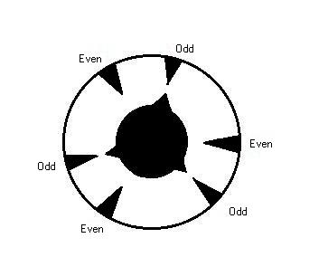
Still confused? Well, a picture is worth 1,000 words. Take a close look at the larger version of this picture (unfortunately the picture is not available). You’ll see each contact on the inside of the HEI distributor cap labeled in green with “Even” or “Odd”. The “even” contacts go to any of the three cylinders on the passenger side bank, the “odd” contacts go to any of the cylinders on the driver’s side bank. The blue numbers 1-6 are cylinder numbers where my wires are connected, yours may be different just as long as you stay with the even-odd concept. The six short lines through the red circle indicate where ignition takes place as the rotor goes around 360 degrees of a circle, the red 45s and 75s are the number of degrees that the rotor turns between each ignition point. Now take a look at the picture below, it is a crude drawing of the distributor contacts underneath the rotor. There are three pairs, 45 degrees between the contacts of each pair and 75 degrees between the pairs themselves. The shaft has three contacts that will line up with the outer contacts six times for every time the distributor shaft rotates.
Installing an HEI distributor
When upgrading to an HEI distributor or simply reinstalling one, follow these steps:
– Line up your engine to TDC on cylinder #1
– Set the distributor down in the engine, make sure the distributor shaft sits down in the oil pump shaft slot
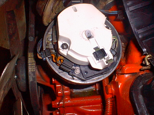
– Remove the rotor from the distributor, rotate the housing so that the contacts line up exactly as you see them in the above right picture
– Tighten down the distributor
– Reinstall the rotor and note where it points, this is zero degrees BTDC on your #1 cylinder
– Install the distributor cap
– Install the #1 plug wire on the cap lobe closest to where the rotor points (make sure!)
– Install the remaining plug wires in a clockwise pattern in the standard 1, 6, 5, 4, 3, 2 sequence
Got it?
Put together all this information about the odd-fire distributor cap and you can see why, unlike an even fire engine, you can’t just turn the distributor to the next ignition point, move the wires around to match and still have a running engine. If you need to rotate the distributor housing you can, but you need to do it by two wires in order to satisfy the even/odd requirements of the cap and distributor. If you’ve lined up your #1 plug to an even distributor contact instead of an odd contact the engine will still run, but not smoothly. This system works well as long as it is installed correctly, so good luck!
References
Thanks to Bill Lagler for helping me understand all this.
Find lots more HEI conversion information at the American Jeepster Club.
The Dauntless V6 picture at the top came from John Hubbard’s Dauntless V6 page. and was originally scanned from a dealer brochure by Mike Boyink.
See more great V6 info at the Adam Sparks’ Early CJ-5 page.
I bought my rebuilt 231 HEI distributor from Glenn Woodworth at Cape Conversions (driveajeep).
The crankshaft pictures came from http://www.gmperformanceparts.com/V690CRAN.htm
The other pictures are from my own Jeep.